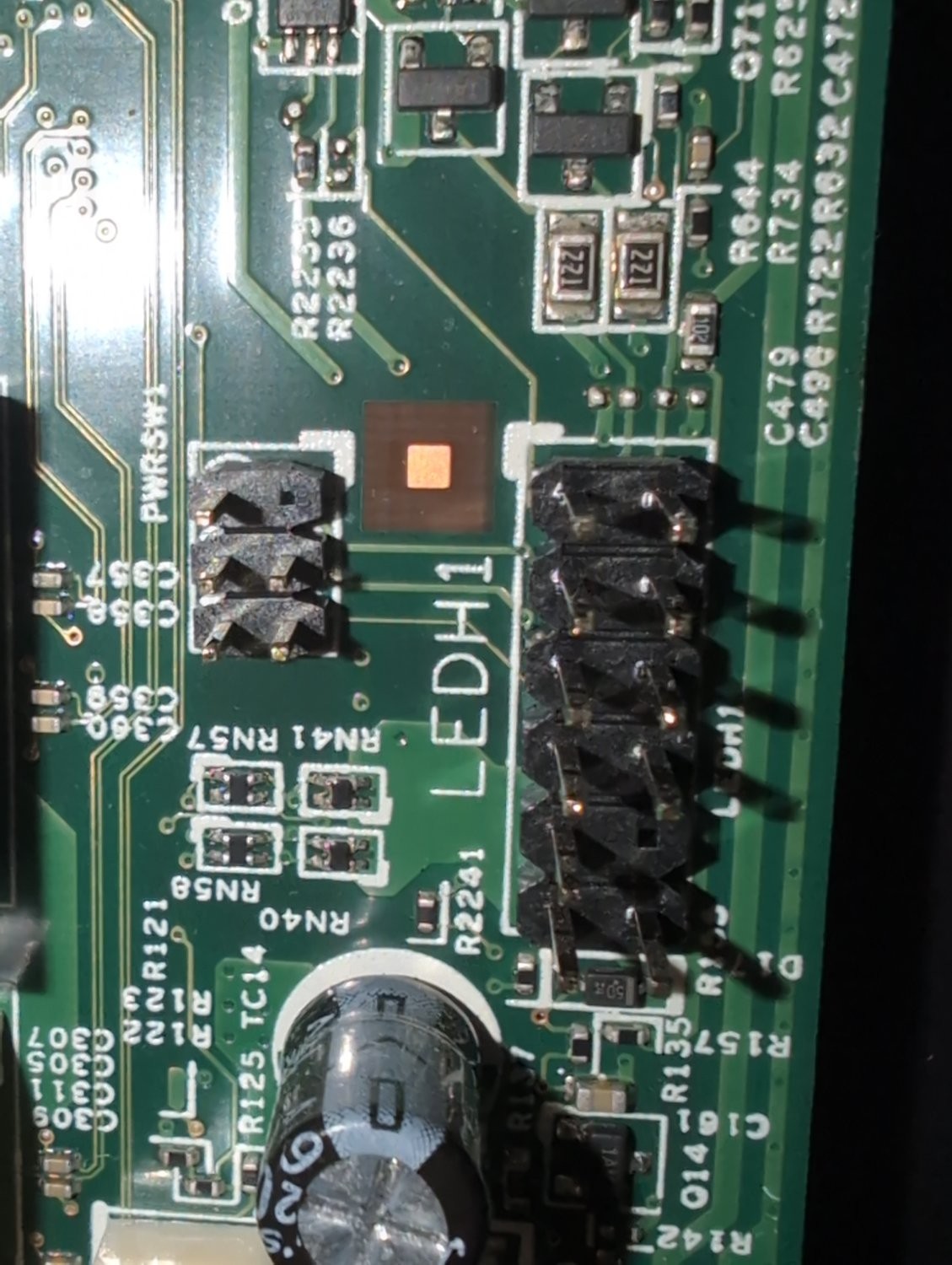
It’s for the LEDs to make your computer go faster.
post
They are proprietary and typically have a pin jumpered to ground as the dell cables sense disconnects. Some dells already have after market adapters. Let me check my notes...
Notes: I bought these, but looks like they don't have your model with 12 pin. https://store.harbinrepairs.com/index.php/product-category/motherboard-conversion-adapters/dell-compatible-adapters/
While waiting on the order I had wired my own with some tiny connectors, after finding a wiring pinout.
https://www.google.com/search?q=ledh1+pinout
Bunch of good results there. First result on the images page has people discussing this exact problem: https://forums.tomshardware.com/threads/dell-inspiron-3847-where-does-the-power-sw-reset-sw-hdd-led-power-led-and-go-on-the-motherboard.2876355/
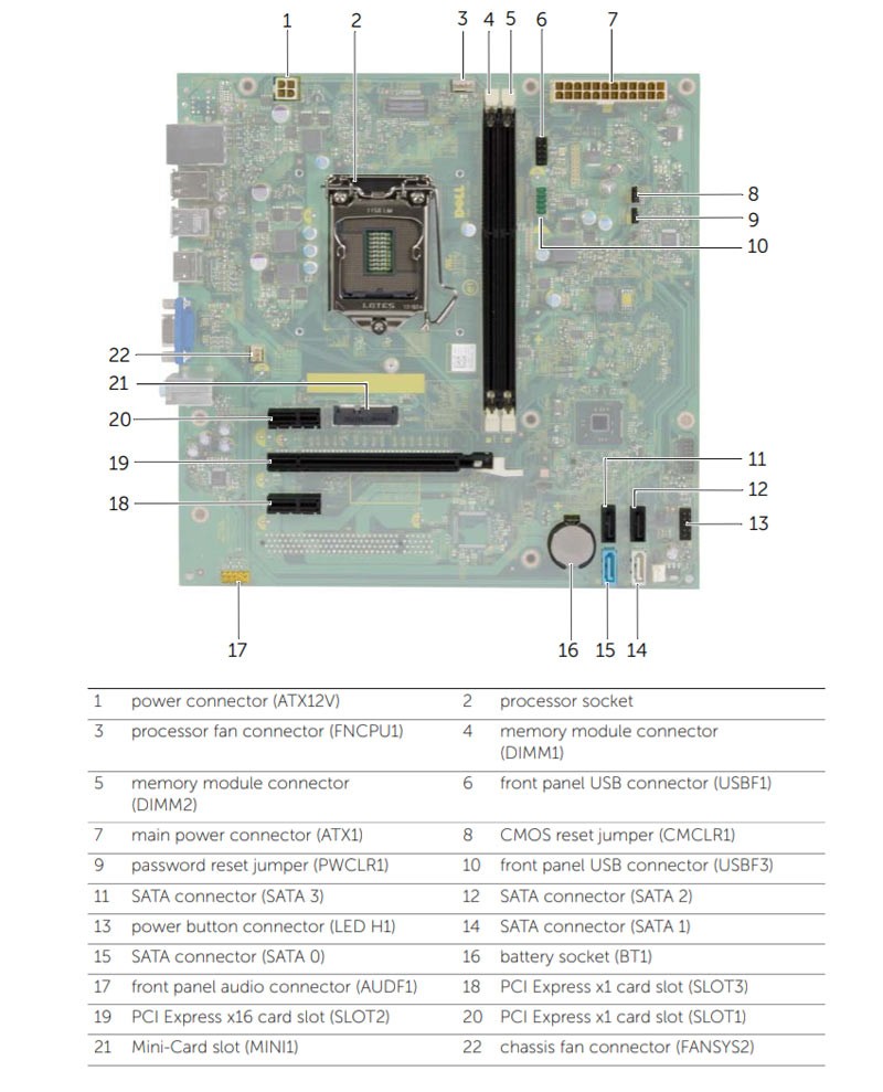
Did you see this from Hardware Corner? You're looking for #6

I did see that graphic. Number 6 is USB though.
Searching, I can see some other people asking about "LEDH1" connectors, so I'd guess that it's probably something Dell proprietary. My own past experience has been that Dell doesn't always use standard connectors.
You can probably trace out the leads if you still have the old case and connector. You do that, get a pinout, you can probably rig up your own cable from the old one and splicing wires.
I wouldn't hassle with it myself, would just get a different motherboard, but if the time tradeoff is worth it to you...shrugs
At this point I'm determined to use this board as I've already put enough time and money into upgrading that shitass optiplex. It's surprisingly usable with Cachy OS.
I did some googling. It's more than just a different pin out, you also have to tie some lines together.
Led, and that many pins makes me think it’s for gamer lights. Any chance they share the same board with a higher end computer?
I’m seeing “PWRSW1” in the cluster to the left.
It is possible to deduce which header is the power switch.
Do you have a multimeter and do you know how to use it?
You want to start by figuring out which pins are GND. Ultimately, you’re looking for a 3.3V signal that is always on.
Connect your power button to a pair of pins that correspond to 3.3V and GND. Pressing the power button pulls that 3.3V signal low, which tells the embedded controller that it’s time to boot up.
If you still have the case, you can also use the connector to make the same determination. With a multimeter set to continuity mode and each probe connected to the right pin, pressing the power button will result in a ‘beep’
all 18 comments