yup that's true, i usually do my work with 5VDC , but i will switch to a Darlington transistor if i need to work with 3.3VDC in the future, thank you for the advise. 👍
comments
comment on
My old 1-channel relay driver circuit works
comment on
My old 1-channel relay driver circuit works
Looks fine. Mayyyyyyybe the 1k resistor is a little high, depends on the gain of the transistor. 5 volts would feed it with 5mA on its base, which might not be enough to fully switch it on. However, as it's only driving the relatively high resistance coil in the relay it's nothing to worry about if it works.
If you were driving it with 3.3V, I'd probably swap that transistor out for a Darlington pair to make sure the gain is high enough to fully switch on at that kind of drive voltage. You can get Darlington pairs in the same pinout as normal transistors so it would be a straight swap on the board.
Having said all that, if it's working in your application, leave it. 🤷
comment on
My old 1-channel relay driver circuit works
for 240V AC this relay can handle 5 Amps
comment on
My old 1-channel relay driver circuit works
The manufacturer has rated this relay for nominal motor (ie inductive) loads of 0.5 A, with peak surge of 2.5 A, at 120 VAC. The flyback diode should be sufficient, since the switching rate would not be very high to control a relay. The terminal block supports a max wire diameter of 1.5mm2 (~16 AWG) which would be more than plenty for a 0.5 A load.
If you're actually running >60 VAC through the relay, then it's good practice to add a slot that prevents creepage currents between the low-voltage DC section and the higher-voltage power section.
For smaller applications, this seems reasonable enough, at least to me.
comment on
My old 1-channel relay driver circuit works
forgot to include this


comment on
My old 1-channel relay driver circuit works
yeah sure


comment on
My old 1-channel relay driver circuit works
I already added solder to the relay contact tracks to increase it's thickness
comment on
My old 1-channel relay driver circuit works
those are for the low voltage control pins for a gpio (to control the transistor and the supply +5v and GND)
comment on
My old 1-channel relay driver circuit works
I think it would help us if you included the part designators for components on the board, and then what your design criteria was. After all, this might be fine for 1A at 5vdc but fall apart for 10A at 67vac.
comment on
My old 1-channel relay driver circuit works
(squints)
Looks fine up to about 6 amps I reckon, judging from the size of that relay. Not a huge high power coil on that so a simple npn transistor switching the coil to ground would be fine. Got a diode across the coil to catch the back-EMF, looks like all the basics are covered .Would only bother adding extra solder to the tracks for the relay contacts if I was doing it but that's neither here nor there.
Dunno what those eevblog folks are on about 🤷
comment on
My old 1-channel relay driver circuit works
I think the connected wires would vaporise before those tracks ..
comment on
(Solved) 9 Pole 1 Throw Switch?
My thought as well. If you get 9 switches that have thin levers, and drill 9 holes in a piece of wood, you'd end up with a wide bar that can move 9 switches at once
comment on
(Solved) 9 Pole 1 Throw Switch?
but I’m not sure how to find one of these with name brand relays that id actually trust in a commercial setting.
I suppose that comes down to "what is the worst case scenario assuming the board fails". If you simply can't have it fail the design should have redundancies built in. If you're looking for build quality/established MTBF ratings then piggyback on top of someone elses regulatory approvals where those tolerances are built in. I just did a quick google search for "relay board FAA approved" not even knowing what the regulatory rules are of aircraft. Apparently those are FAA-PMA and TSO. Plugging that in with "relay board" and you get something like this:
Sandia Aerospace 12 Pole Switching Relay

This level of build quality and certification comes at a much higher price of $524 for one board though. Another choice I might chase would be "medical".
comment on
(Solved) 9 Pole 1 Throw Switch?
Using the NC side of the relays would be the best way too, but I’m not sure how to find one of these with name brand relays that id actually trust in a commercial setting.
comment on
(Solved) 9 Pole 1 Throw Switch?
That would be 1 pole 10 throw, OP wants 9 pole 1 throw
comment on
(Solved) 9 Pole 1 Throw Switch?
They are rare but they do exist, eg: https://www.salecom.com/en/product/wpt.html Hope that gives you some idea of what they look like and what search terms to use
comment on
(Solved) 9 Pole 1 Throw Switch?
Is this using a 24v AC setup or is it DC? I feel beyond the logic of what you're trying to do, this could be important.
comment on
(Solved) 9 Pole 1 Throw Switch?
Search for “10 position rotary switch” - there are lots of options :)
comment on
(Solved) 9 Pole 1 Throw Switch?
If I understand what you're describing, I'd probably use a relay board. They're not expensive:

You could wire all of the control circuits to one wire, and with the flip of one switch on the control circuit turn on/off all 10 relays on their load circuits.
comment on
(Solved) 9 Pole 1 Throw Switch?
Not sure exactly the size of switch you're working with, but couldn't you get or fashion a coupler that mechanically links multiple switches together...
I'm thinking like they do with circuit breakers like this:
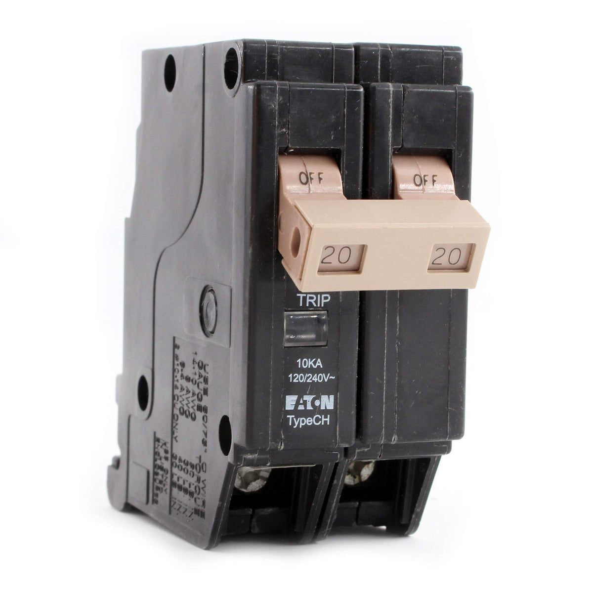
comment on
Turn membrane button into mechanical button?
The few items I have in mind have hard boards with a little rubber foot that touches either two half circles or two wiggly lines, though I do have one of those plasticy ones you're taking about. What if I trace the lines back to the board and replicate it with wire?
comment on
Using open source tools for FPGA development
Are you a student in Istanbul too?
comment on
Using open source tools for FPGA development
[deleted]
comment on
Using open source tools for FPGA development
One question is if you will be using some Xilinx IP, in which case the simulation models likely will be encrypted. If your project doesn't, I don't see why it would be an issue using Icarus, etc.
If all you depend on from the IP is data over an AXI/AXI-stream or the like you can use open-source bus-function models (which I understand as librarues you can use that will take care of properly driving something like an AXI interface for you) in your testbench.
I'm a student myself, Im sharing what I know but this might not be how industry does it.
And I'm criticizing the criticizer of the criticizer of the helper. ☝🏼
view more:
next ›