[–] 1 point 5 days ago

Not OP. I totally get your vibe, that's been my attitude with prostelyizers before. I was raised in bad religion.

These days I look forward to talking to them. That whole "planting seeds" thing works in both directions.

I try and plant "seeds of doubt. ' Paradoxes and fallacies in the Bible such as the origins of tithing, the problem of omnipotence and suffering/evil, systems of control, etc. It's a lot of fun.

  • source
  • parent
  • context
  • [–] 4 points 1 month ago (3 children)

    Ah, Mr. Hands. I'll never forget the grunt Mr. Hands makes when the horse perforates his intestines.

    There's actually a documentary about it. Dude had spinal damage that caused sexual dysfunction. Resulted in Washington state passing a bestiality law.

  • source
  • parent
  • context
  • [–] 8 points 2 months ago

    I totally skimmed what you had written as it was pretty inchoherent. If your politics have become so esoteric that Lemmy users can't parse them, that's a 'you' problem and you might want to examine it.

    Like, the barrier to entry of Lemmy filters users here such that: most people here tend to have above average intelligence and reading comprehension.

    So, you're either posting AI crap, or have gotten so twisted on some kind of propaganda that you can't meaningfully comminciate with others. If you're actually human you shoild probably unplug from your political ideology source and talk to an old wise hippy or something.

  • source
  • parent
  • context
  • [–] [S] 1 point 3 months ago

    Why make this harder? A constant frequency simplifies the analog design

    I wasn't planning on variable frequency, you were speaking to the influence of frequency on voltage output earlier. I just meant that I could vary the frequency without messing up synchronization of the waves. I.E. I can produce two square waves of arbitrary duty and frequency up to 625kHz. The higher the frequency, the less resolution I have, however.

    Anyhow, the output will be filtered with at least some fat caps. My load is a static resistance (heating element). I could probably drive this thing with a 555.

    As far as I know, the Atmega328, at least, can't use the ADC to bypass the CPU and directly set the timer registers. The ADC can throw an interrupt and then the CPU sets the timer. When your pwm frequency is sub 100kHz, there is plenty of time to change the duty.

    I don't know that I will need to vary the duty with logic. It's just an idea I had that seemed neat. Quick coarse adjustment and then a fine tuned adjustment.

    I'm teaching myself about SMPS, and I'm curious. While the final circuit will have utility. I'm really learning how to use a scope, the newer AVRs, and switch mode power.

    Everything has switch mode in it now, my vehicles, my arc welder, every chunk of electroincs pretty much. It's treated like a black box, buy the chip, follow the data sheet. However, if you want to build or fix one from first principles, good luck. Most approachable reference I've found is the DC/DC Book of Knowledge by Steve Roberts. And even it assumes that you'll mostly be using an ASIC.

    Generally, I come up with an idea in electornics or programming that is novel to me, somebody else figured it out decades ago. That's why I'm wondering what you call the minumum pwm resolution and whatever this fast dumb logic adjustment to duty is.

  • source
  • parent
  • context
  • [–] [S] 1 point 3 months ago (1 child)

    I explained it poorly. The chip has an ADC that can operate in window mode. I. E. when my output voltage jitters high or low out of bound, I can use logic to very quickly effectively increase or decrease my duty cycle. (Actually substitute another pwm signal that is in pnase but with a larger or smaller duty)

    5V square PWM from the ATtiny goes to a gate driver capable of several amps at 5V, that gate driver switches a pair of logic level MOSFETs, one of the MOSFETs switching the coil and the other acting as the recitfier. Topology is a synchronus inverting buckboost.

    Changing the duty cycle then raises or lowers the voltage.

    At the same time, via interrupt or event channel, the cpu starts calculating a new duty cycle and setting the timers. Interrupts may take 100 cycles. Whereas, pwm at 625kHz will have completed an additional three cycles before I can even start to modify the duty from the program.

    None of this may matter. Static dumb resistive load, I could probably just about run my MOSFETs off a 555 and not even worry about feedback or regulation.

    However, the idea is interesting to me. Quick response regulation with more precise regulation happening as the CPU catches up.

    Seems like it would give you a flatter output.

    I've found when I discover an interesting electronic or programming technique or problem, that usually means I don't know the name. It's usually something figured out decades ago and there are references and papers that explain it and consider angles that I didn't know about.

  • source
  • parent
  • context
  • [–] [S] 1 point 3 months ago (5 children)

    Gain bandwidth seems to be really analogous to what I'm trying to figure out. If I can't find a version that is more digital/pwm specific: it will probably be easier for me to figure out what minimum resolution I need experimentally.

    I'm looking at a constant frequency, variable duty drive as that seems the simplest. Also, the higher I can get the frequency, the less ripple I'll have to deal with. However, there's nothing really stopping me from doing variable frequency.

    The timer I'm using is TCA. I haven't tried it yet, but it allows buffered register changes. I.E. the registers where I'm setting my duty and period can be updated in sync with the waveform. So, in theory, I can vary my waveform frequency and duty cycle all over the place. I'll actually be using two of these signals, the other will be for a mosfet in place of the rectifier diode. Dead spacing shouldn't be any trouble.

    I may even be able to use the programmable logic to combine 3 pwm signals into one per channel. I will have the spare internal outputs available.

    I'm still kind of studying on this and probably need to draw a picture. Say you have 3 square waves that all have the same period. They are synchronized on the rising edge. 1st signal is 25% duty, second is 50%, and the third is 75%. Depending on what a comparator is reading, your logic selects which signal to output. 50% to maintain and the others to drop or raise the voltage.

    So, if your voltage goes out of bounds, high or low, within a single clock cycle your square wave can be adjusted by some amount (25% amounts are just an example.) At the same time, your cpu begins grinding cycles to reset the buffers to adjust everything to a new duty center.

    It would probably be a small amount of fast logic adjustment. At a guess, 10% or less.

    I apologize if this is confusing and will draw it, if needed.

    Any idea what that would be called?

  • source
  • parent
  • context
  • [–] [S] 2 points 3 months ago

    The period is divided up into 32 pieces, instead of a 256 bit width, if that makes sense. So, the frequency is 20mHz/32 = 625kHz. 0b100000 / 0x20.

    Yeah, and with the load I'll run, it's not real critical. I just figure there has to be a name for this sort of tuning. If I know what it's called, I can read up on it.

  • source
  • parent
  • context
  •  

    So, I'm tinkering with the ATtiny 3224 and its PWM capabilities. I can get 256 bits of resolution per cycle at 78.125kHz.

    If I drop to 32 bits, that gets me to 625kHz, as shown in the screenshot.

    I've done some searching but I may not know the right term and I'm probably looking for a rule of thumb.

    What sort of resolution do you need to regulate a DC/DC switch mode? (in this case a pure resistive load that doesn't change)

    I think it might be something like a factor for required percentage of change of switch ON time. Such as, you should generally be able to modify your duty cycle by increments of 5% or 0.5% or whatever for proper regulation.

    Does this factor have a name?

    [–] [S] 1 point 3 months ago

    I'm looking at the FAN3224, a gate driver capable of several amps at 5V to run my MOSFETs. I'll probably play with direct driving them with the ATtiny at first just to familliarize myself.

    The original circuit is running some sort of bridge configuration. I've used a 1.6ohm load for years, with wattage set to 14.5 or 14.8. However, the orignal is capable 25w in the lowest output version. I'm not sure what resistance range it's capable of pushing that 25w.

    And, yes, the goal is to build a variable DC supply. I'm finding it really interesting. I'm looking at the synchronus inverting buckboost. I think my final version would use half the components of the original.

    If I understand this stuff correctly, (real big if), with the convertor pushing negative voltage, I sidestep high side drive problems. My load is dumb resistance so it doesn't matter how noisy or negative its power is.

    So the ATtiny has an ADC capabale of running in windowed mode. A lot of the peripherals are able to run independently of the CPU, you can link them up with onboard programable logic called CLC. So, using logic I can tie the ADC to my PWM at pretty fast speeds. It also has a selection of internal voltage references. I'm planning to use some sort of voltage divider for feedback to the ADC, using the logic to vary my duty cycle when the voltage goes out of bounds.

    Before I get that far out in the weeds, I need to play with mosfets, pwm, an inductor, and my new scope.

  • source
  • parent
  • context
  • [–] [S] 1 point 3 months ago (2 children)

    Plan is for the ATtiny to actually mostly be asleep on the battery voltage. The 5V driver IC has an enable pin and goes into bypass mode when it's not enabled. Only when it wakes up will it turn on the 5V.

    I want the 5V for the 4.5V gates on my MOSFETs, the OLED display (IIRC, it will also run on 3.3V), and the 20mhz for PWM and ADC.

    DC/DC convertor. I'm hoping I can make a synchronus inverting buckboost supply in the neighborhood of 25w/6V max.

  • source
  • parent
  • context
  • [–] [S] 1 point 3 months ago (4 children)

    I'll be reading up on push-pull. Thank you!

    Main power source is a single cell lithium, so 3.7ish volts. Supply for the ATtiny is a 5V driver IC (I've already got it working).

    The convertor I want to build will be inverting as the load is basically a pure constant resistance. (14.5w 1.6 ohm typical). I think that means I sidestep all the problems with a voltage higher than my control.

    I'm hoping to use the window mode of the ADC and the programmable logic (CLC) to actually control the convertor mostly independent of the CPU.

  • source
  • parent
  • context
  •  

    I'm tinkering with the ATtiny 2 series (ATtiny 3224). I'm also starting to teach myself about switch mode power and surface mount design. I'm planning to drive two Toshiba SSM6K804R MOSFETs. They are logic level MOSFETs with a 4.5V drive. They have a gate capacitance of 1110pF (1nF).

    Even though these are logic level MOSFETs, I think I still need an external gate drive for them for crisp switching above a few kHz. I don't need to try and charge the gate directly with the ATtiny as I would need a 2-300ohm resistor in series to protect the microcontroller and that will slow everything down. Also need a pulldown for the gate.

    Can someone please recommend a simple IC or maybe a packaged transistor pair that I can slam the gates with?

    Questions/comments/advice greatly appreciated!!


    I received email and Jerboa notification of a reply 6 days late. Respondant is on a different instance (lemmy.cafe). I don't know if it's a federation/propagation issue, problem may also be on their end.

    Link to comment.

    Not a huge deal, but I thought y'all might want to know. I didn't see any threads on this after quick scan of support.

    *edit typo


    I'm working through Modelling & Sculpting the Human Figure by Edouard Lanteri. This bust is used as the example for sculpting the head. Lanteri is working from a plaster copy of the original.

    On pg. 39 he gives the title as 'The Lawyer' by Donatello. I haven't been able to find this sculpture attributed to Donatello.

    For the earlier examples he's using Michaelangelo's David and I've been able to print my references. I was hoping to find a model of this sculpture as well.

    Can anyone please give me more information?


    Due to CAD/CAM and the nature of my industry, I'm stuck with windows on my daily driver for the foreseeable future. (Been using Linux since Ubuntu was new, have multiple servers and old chromebooks running different flavors.)

    I've been putting off dealing with this. Goatfucking bullshit pain in my dick. Ffffffuck me right in the ass. I would happily slit Clippy's throat right in front of his little paperclip children and sleep like a baby.

    Can I pretty please get recommendations on upgrading to 11 and unfucking it as much as possible? Comfortable editing the registry, using the command line, and monkeying with the BIOS. Anybody know of a good guide for neutering all the AI shit, copliot, onedrive nagging?

    *Edit - Solved:

    Thank you all very much! This is the advice I was looking for.

    Long ago, I learned that when preparing to do a machine incantation; you must give the machine a good cussing. It shows the machine you are the boss and the machine gods are more likely to smile upon your efforts. I have a black cat and crossroads dirt in case things get real bad.


    I recently acquired an old electro-cautery unit. Think it is from 1910s or 1920s. Has a big old multi tapped torodial transformer running to a couple of connectors/poles. It is by F. Geiger of Philadelphia. Wood case is labeled 110V. 60 CY. and 4V. 100A. Seriously old school cool and a little horrifying.

    Insulation on power cord was brittle as was insulation from secondary to pole. Both have been replaced. I used crimp connections on the primary wires (didn't measure gauge but it's on the order of 20 AWG). I was in a hurry to test and will eventually solder it properly. I added a switch to the new power cord.

    It works with output voltage varying from 0.1V to 4V. It gets a woodburning tip glowing orange at setting 4 (2 volts or so). Should make a great woodburner and be useful if I ever need to interrogate someone.

    There isn't really a way to ground it and the screw on the control knob is electrically connected to the secondary. I have a gfci adapter that I could plug it into. Basically, if the transformer shorts, 110V could be exposed on the face.

    There are two holes on the face plate, the power cord is running through the largest and the other is empty. It may have had a foot pedal.

    I want to add a RGB indicator light for voltage level using the small hole. It's a little tricky to tell when the tap is lined up and you're getting voltage. A green - yellow -red fade and maybe white for NC. I have a spare Arduino Nano clone, but am not sure what circuit to rectify the AC with for the ADC. Maybe an Op amp follower? Power supply would be a 110-5v usb charger board. I would prefer to avoid a dual rail supply or higher than 5v.

    Thoughts and suggestions appreciated!


    Trying to get a better understanding on the whole tankie thing, found this study that seems unbiased. It looks at their online behavior. I would appreciate others review of the study, even if just bullshit or facts.

    Jeebus these people are exhausting, they also spray so much disinformation. They remind me of MAGAts.

    I don't yet have a feel for the dynamics like I do with MAGAts. How much of it is organized with handlers and such vs. organic true believers?


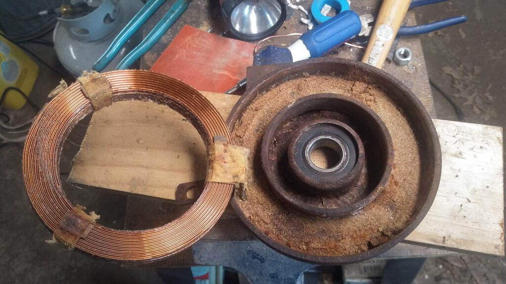
    The electric PTO clutch on my 1969 mini tractor is dead and discontinued.

    Original winding is aluminum 18 gauge. Manufacturer specs were 2.88ohms, 237 turns. The manufacturer specs didn't quite physically match what I found when I took apart the old clutch. If I understand this correctly, the 2.88ohms is the most important part and will pull 4.17 amps.

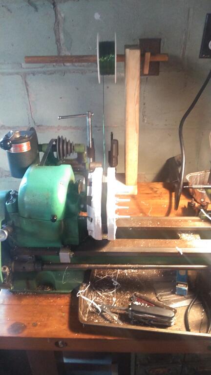
    I just attempted a coil with 18 gauge copper magnet wire. I made it to the max dimensions I can get in the housing with a scramble wind. I'm getting 1.2 ohms, which would pull 10 amps or so. Not good.

    Was able to get 187 feet given the resistance.

    If I go with 20 gauge copper, assuming I can get 235 feet (1.26 * 187) and I should get 2.319 ohms. Probably get a little more than 235 feet and get the resistance up a little more.

    What does this do to the strength of the magnetic field?

    Would I be better off putting a power resistor in series with my 18 gauge coil?

    Any advice greatly appreciated!


    I hurt. I hurt all the the fucking time. My belly hurts. I'm reducing my drinking but it really sucks. The withdrawals suck real bad.

    Lost my colon to U.C. Have a bag on my belly.

    I have to move my family out of the south. I have to be physically able to do it. We have to get out.

    If I get them out maybe I they'll be able to live happy.

    I just want to die. I want the pain to stop. I don't let my people know. They can't do it without me.

    I'm tired. I hurt all the time. I'm tired of hurting. I could turn it off, but I don't for now. I'm tired of the pain. I love them and they need me. I just want to make sure they're in a good place, away from here. Then I can finish it.

    view more: next ›