[–] 4 points 1 year ago (8 children)

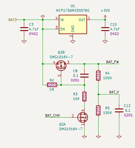
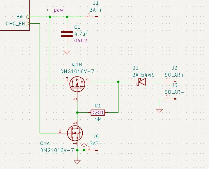
The toner transfer method would be I think the most DIY method you can use. Make your pcbs entirely by yourself at home.

Naturally wont give you as professional a result: no silkscreen, limited to 2-layer pcbs (2 sides of a copper plate).

But it is a lot faster that having it manufactured (takes me like 1 hour for a pcb) and maybe this is debatable but it makes me feel like I have more room to make mistakes.
  • source
  • [–] 5 points 1 year ago (3 children)

    If I recall, Altium has a free tier, it's my driver for work, so I use that. As for acquiring a designed board, jlcpcb is a good, inexpensive PCB fab (there are others, but jlc has been surprisingly good for my use)

    If you need assembly, too, some do it, it's not cheap though.

  • source
  • [–] [S] 2 points 1 year ago

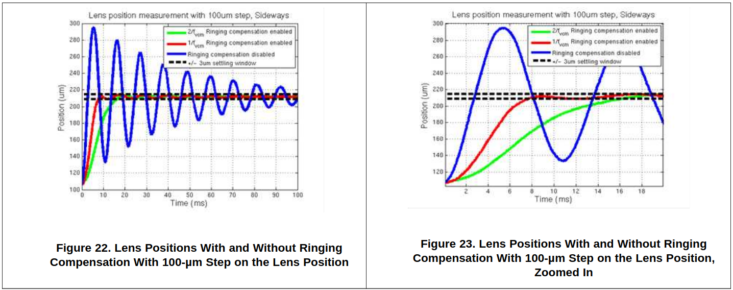
    The ringing comp is interesting: it's completely synthetic (sensorless). The chip models what it thinks the ringing should be based off some physical parameters (that can be configured over I2C), then drives the coil in a way that it hopes would counteract the ringing, but never actually knows if it has succeeded.

  • source
  • parent
  • context
  • [–] [S] 1 point 1 year ago

    Similar to how you can do current sensing in motors

    I do not think there are not enough variables here to make this work. Reading coil current won't give you any information you don't already know if you're already controlling coil current. You need to be reading at least one more variable that is somehow related to coil position.

    Turning off the coil drive and shorting the coil temporarily to measure current is unlikely to give you anything but the same current you were driving it with (minus some losses). Ie still not an extra variable.

    you can send and receive with the same coil in a metal detector.

    This introduces new variables! Reflected signal magnitudes (and distortions & phase delays) that depend on distance to a nearby metal object that you intentionally install near the coil (eg the metal casing).

    Not sure how easy or reliable this would be to do in practice. I have my doubts but I could be wrong :)

  • source
  • parent
  • context
  • [–] 1 point 1 year ago* (last edited 1 year ago) (1 child)

    I never worked with these before, but these coils are apparently called "Voice Coil Motors" (VCM). The one from this post is big but its the same tech that is used on a smaller scale in phones.

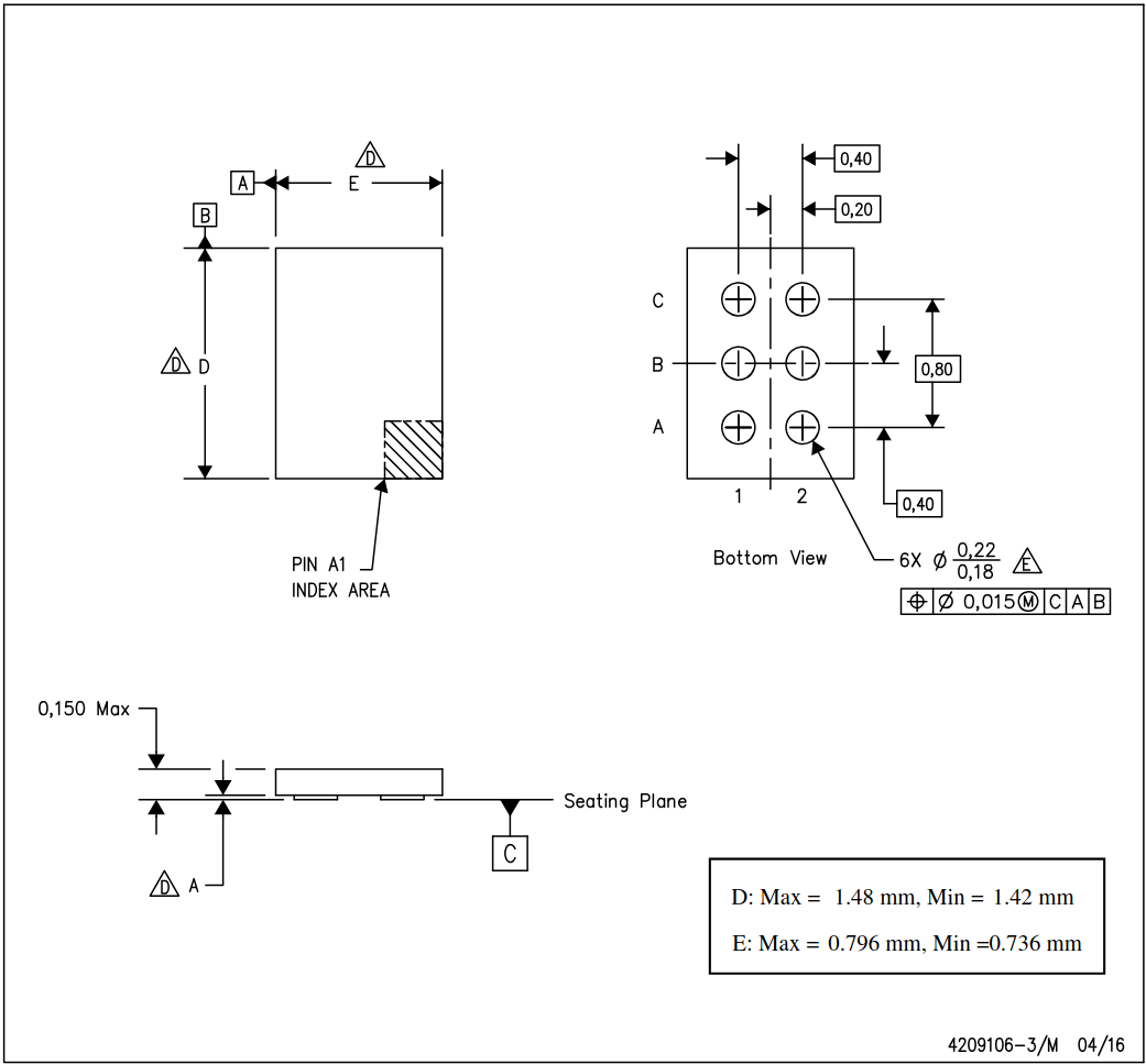
    I went and found a "driver" for these things and took a look at the datasheet to understand how a VCM is typically controlled. This thing is 1.5mm x 0.8mm small so something you might actually find in a phone.

    The driver chip has built in current sensing and the current going through the coil directly corresponds to lens position so just from that, the driver knows where the lens is positioned.

    https://www.ti.com/lit/ds/symlink/drv201.pdf#page=8

    The device is used to control the current in the voice coil motor (VCM). The current in the VCM generates a magnetic field which forces the lens stack connected to a spring to move. The VCM current and thus the lens position can be controlled via the I2C interface and an auto focus function can be implemented

    Because the lens stack is spring mounted it can lead to "ringing" which basically means bouncing that continues after the desired position was set. So the chip apparently has built in logic for compensating for that so it more smoothly reaches the desired position without overshooting.

  • source
  • parent
  • context
  • [–] 2 points 1 year ago*

    Uhmmm… I am not an expert, but what if use a second drone, one for TX and one for RX? Isn’t it just what IceEye does in the space with satellites? With GPS based time synchronization this could not only be feasible but at least decrease the noise floor from lack of TX-RX leakage. Would it also increase the angular resolution? Any other benefits?

  • source
  • [–] [S] 3 points 1 year ago

    After I read this, I thought it would be really cool to try to make this myself. But then I realized I'm barely able to get a simple circuit working much less one that involves complex RF signalling.

  • source
  • view more: ‹ prev