1


cross-posted from: https://lemmus.org/post/26646894

a website to help students visualize the electromagnetic field

I’ve been building this simulator as a side project aimed to help students understand and visualize electromagnetic phenomena such as radiation, near field effects, polarization, wave interference and diffraction.

You can:

  • place multiple, diffrent radiation sources and set their parameters (geometery, amplitude, phase and more)
  • place perefect wire conductors, PEC plane and poke slots in the plane to create diffraction patterns
  • observe the electric field, magnetic field, energy flow field, energy density or radiation pattern
  • zoom in and out and translate the canvas
  • change the simulation resolution, frequency and propogation speed and some other parameters

I hope someone might find it useful and I’d love to hear what people think :)

What do you think I should add?

Live:
https://www.antennasim.com/

GitHub:

https://github.com/rotemTsafrir/antenna_sim

2


Midland Model 74-102. Manufactured February 1989. I found this in a thrift shop yesterday. It had a 9V battery so I gave the dial a turn, and sure enough, it still works!

I can't justify the cost of a new weather radio, but this guy only ran me four bucks. Now I need to get my hands on a 12 volt barrel jack power supply.

3


cross-posted from: https://feddit.uk/post/56789745

DeviceI had this cheap chinese radio MIABOO M20, which had a ton of cool features: portable, bluetooth, aux, and radio. But the speaker wasn't great (mono), and the battery didn't last very long

So I took it apart (beer, force, pliers) with great effort since there's not a single screwhole anywhere on it as it was all glued together

Components:

  • Speaker
  • Battery (no markings, but big and blue cyclinder, looks like a 18650 Li-ion)
  • Main board
    • 2-pin JST speaker connection and another 2-pin JST (2.4mm pitch)
    • SD card slot
    • MCU, unknown 18140
    • 18-pin FPC connector to the LED board
  • LED board
    • 54 Lights:
      • 4x5 grid of different coloured LEDs
      • 4 digits with colon and a dot
      • 4 bottom lights
    • 4 buttons
    • 18-pin FPC connector

LED Board

Front

7 sets of something that appear to feed into everything else. My guess with the 54 LED lights is that it's probably a 7x8 grid, and this is the "7" part.

Some markings on the board:

  • Q are where the transistors are
  • 2A I think are fuses?
  • 104 and 102 are common resistors, with R names etched into the board
  • O are the test contacts on the board -- little circles of metal for me to test with a multimeter

     [O2]             [O14]

       Q5    Q4      Q7     Q6     Q8    Q10     Q9
    | 2A|  | 2A|  | 2A|  | 2A|  | 2A|  | 2A|  | 2A|
    |104|  |104|  |104|  |104|  |104|  |104|  |104|
    |102|  |102|  |102|  |102|  |102|  |102|  |102|
   R41 [O4] [O5]       [O7] R42  [O8]   [O9]   [O10]
   R47      R40   [O6]      R50   R44  R46    R45         [O12]
            R48     R43    [O15]  R51  R52    R53
  [O1] [O3]         R49                       [O18]
                                                       [O13]
                                                
      |  02  04  06  08 10  12  14  16  18|     [O16]         
      |01  03  05  07 09  11  13  15  17  | [O17]          [O11]
      | F P C - C O N N E C T O R - P I N | 

So the 18 pins of the FFC cable (flat flexible cable?) are shown in the above FPC connector.

I used a multimeter in continuity mode to trace each pin to each of the contacts, and wrote down when it beeped. I then changed the numbering of the O contacts in the above schema so that each O number corresponds to an FPC pin (e.g. FPC Pin 18 traces a path to O18 on the board)

Back

  • Back has all the lights, see the video

Investigating the Board

So I hooked the 18-pin 0.5mm pitch ribbon cable into a 0.5mm FPC breakout board (5 quid, ebay), and then stuck each pin into a GPIO on my Raspberry Pi for testing.

Charlieplexing

I've talked about charlieplexing in a previous post, but the main gist is that pairs of pins, 1 high and 1 low is what drives a single LED. I assumed this was the case with this LED board, but when I tested every single pair against every other pair, I got nothing. Not a blip.

Broken lights?

At first I thought I'd somehow botched the board when I was taking it apart, and was worried that the LEDs were simply broken. I didn't know what to do, but after reading a bit I found out that a multimeter is the perfect tool for this because it has something known as Diode Mode which lets you literally put one probe on side of a diode, and another probe on the other side, and then it shoots a little tiny current through it.

At first I thought this was just mumbo jumbo, but thought I would give it a go, and - OH MY GOD IT WORKS! - each LED I tested this way sparkled light at me.

So I knew the board was working! I just have to figure out how to use the pins to get the signals down there.

Actual broken lights

Okay, so in my excitement in this discovery of Diode Mode on a multimeter, I then packed it away and got out my USB-to-TTL chip which also has VCC and Ground contacts.

For some reason I thought I would just double check an LED again using the 5v from the USB and the Ground on an LED, and.... nothing happened. Wondering what happened, I tried the 3v3 from the USB and the Ground on the LED, and.... (-PEW-) I smelled something burning.

I saw a little puff of smoke rising out of a blown LED, and wondering what happened, I stupidly did again on another LED, and another puff of smoking.

Oh dear

So what happened? Well it turns out that circuits have resistors and fuses for a reason, and that if you run an unrestricted current across a sensitive diode, it's probably going to blow up.

🫢

The reason why the multimeter is the better tool here, is because it gives a teeny tiny 1-2mA between the probes, and a USB can give 1000 times amount. Yeah....

Live and learn.

:

Multiplexing the PinsSo charlieplexing from the previous section did not work, meaning that the board probably isn't completely GPIO driven, but might actually have some dedicated pins for power and ground.

Which one's though?

Not really knowing what I was doing, I connected the LED board back to the main board via the FFC ribbon and powered on the main board. A few lights lit up (yes, this would have been an easier test earlier with the lights), and then I started measuring the voltage difference between each of the O pads.

spoiler O Pad voltage matrix

O\O 1 2 3 4 5 6 7 8 9 10 11 12 13 14 15 16 17
1
2 2.9
3 -0.3 -3.2
4 .14-.17 -2.8 .4
5 .14-.17 -2.8 .4 0
6 .14-.17 -2.8 .4 0 -.002
7 .14-.17 -2.8 .4 0 0 .001
8 .14-.17 -2.8 .4 0 0 .001 -.001
9 .14-.17 -2.8 .4 0 0 .001 -.001 0
10 .14-.17 -2.8 .4 0 0 .001 -.001 0 -.001
11 0.05 -1.2 1.9 1.5 .7 .3 -.05 .3 .3 .3
12 .8-1.1 -1.7-2.0 1.1-1.4 .3-.6 .7-1.0 .3-.7 .4-.6 .7-1.0 .7-1.1 .3-.6 -.3-0
13 .45 -2.4 1.1 .7 .7 .3 .7 .7 .7 .6 0 .4-.7
14 .97 -1.5 1.6 .8 .4 .4 .4 .4 .4 .4 .65 .5-.8 .3
15 .49 -2.4 .3 .3 .3 -.04 .3 .3 .3 .3 .06 0-.4 .74 -.8
16 .5 -2.3 .8 .02 .01 .4 .4 .4 .02 .4 -.3 .1-.4 -.3 -.3 -.8
17 .4 -2.4 .3 -.05 .7 .3 .7 .7 .7 .3 0 .4-.6 0 0 0 .8
18 .3-.7 -2.1--2.5 .6-1.0 -.04 -.05 -.05 -.05 -.05 -.05 -0.04 -.77 .3-.6 -.7 -.8 -.4 .4 0
:::

Great..... what does any of this tell us?

Well there's a pretty high chance that the 2.9V that I got when I put the red probe on 1 and the black probe on 2, gave the highest the positive voltage across the board is the main power line (Pin 1).

There's also a pretty high chance that the -3.2V I got when I put the red probe on 2 and the black probe on 3 is the main ground line (Pin 2). So I think the board operates at roughly 3.3 V, and the first two pins are power pins.

Okay, and does this work?

I moved Pins 1 and 2 in my initial setup on the Raspberry Pi to the 3v3 Pin and to the ground, and yep, things started lighting up!

I assumed that the rest of the lights were charlieplexed, and so I did pair testing on the other 16 pins, and I started getting individual LED's to light up!

Using this information I started to write a little driver and will start using this for my halloween projects!

4


Any good options that are smaller than PC keyboards, but larger than a blackberry keyboard?

I was interested in the Rii but I'd prefer something wired (I2C or SPI)

5
6
 
 
7
8
9


I got and old kindle 8th gen (SY69JL) for free, 'cause it couldn't connect with any wireless network. I tried to do the bridge for popcorn hack as seen here (https://kindlemodding.org/jailbreaking/Legacy/Popcorn/KT3.html). Stupid as I'm, I used the 60w solder and I thing I ripped one of the pads. The damn thing doesn't turn up (not even the led) or shows at lsusb. Is this now just an e-waste? It gets a little warm when puggled on the usb.

10


TL;DW: turns out e-paper has become so good that a 1bpp image can be drawn, whithout ghosting or flashing, at 1/60 s. However, the controllers these displays ship with don't have the memory bandwidth like TFTs to enable this... until now thanks to an FPGA wizard. His monitor is a direct LCD replacement and can switch between high-quality (greyscale/high-color), fast (dithered black/color dots) and power-saving (like low-bandwidth controllers nowadays) modes automatically based on content and user preferences. Everything is open source with off-the-shelf panel and FPGA. The project is finished and is accepting preorders.
Consider watching despite this "spoiler", it's very cool.

11
12


I want to count and log the BPM of a rather large bass speaker (250-400W RMS range i assume).

BUT there is a mostly wooden/stone wall (~40cm) between me and the speaker + a 50cm air gap.

I managed to detect the speaker with a normal microphone, but that gets confused once there are other noises like talking or foot steps in the room.

So my idea was to build a large coil around some graphite rod to build a sensor for electromagnetism. Then connect that to a audio amp and feed the result into a audio card microphone input.

Would that maybe work? Any guesses how far the magnetic field of a bass speaker is detectable? How much wire should i use for the coil?

Edit:

So i found this video https://www.youtube.com/watch?v=83edokt3K5c of someone using a giant coil to pick up a very small speaker from a few feet away, so i assume its 100% possible, and the speaker i am trying to pick up has like 200-300x the power of what he is picking up in the video.

13


Just a neat, theoretically-eternal circuit.

More details and a schematic

14
15


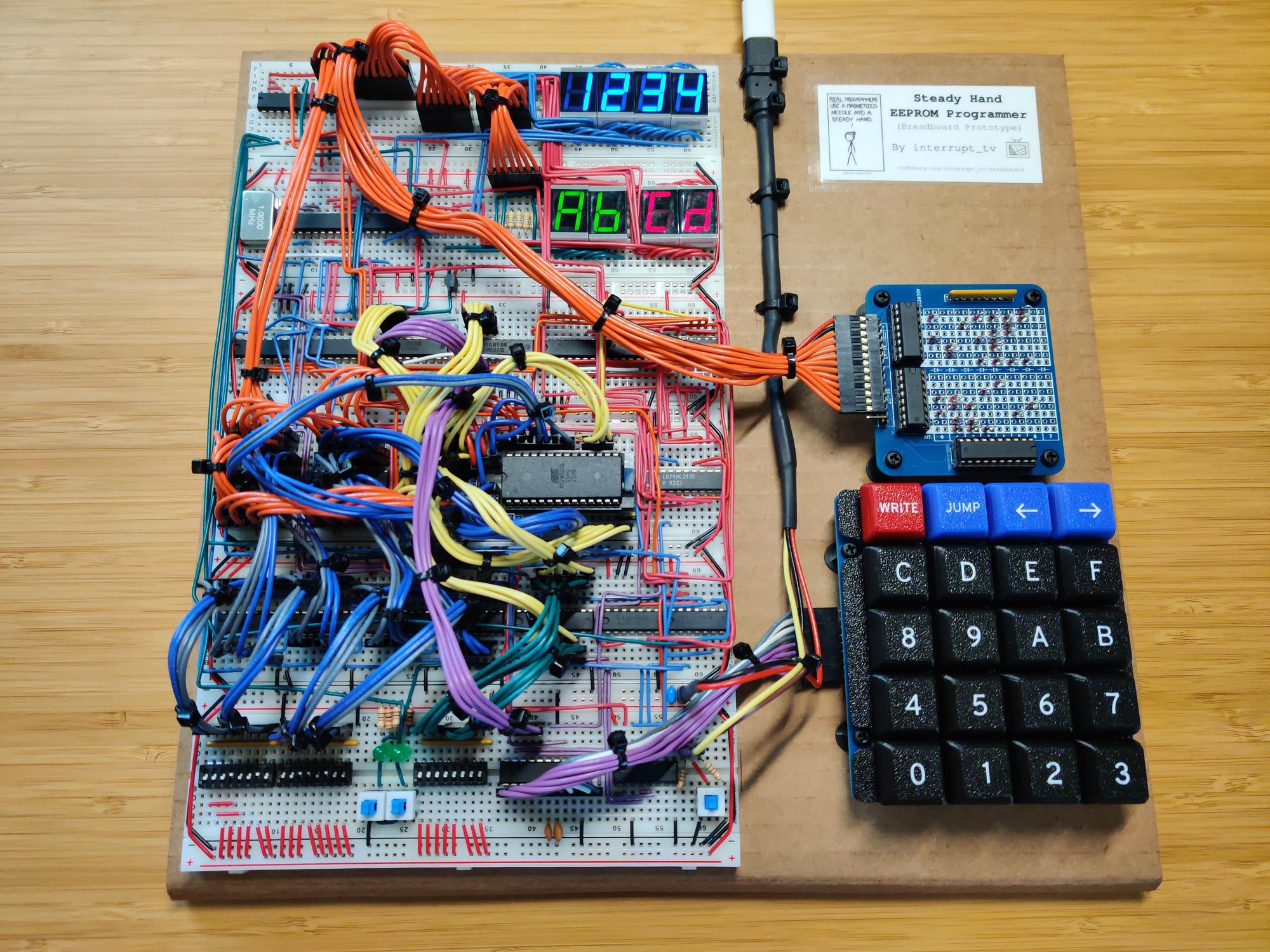
After about 6 months, my project is finally complete. It's the first significant circuit that I've designed myself, rather than just implementing someone else's design:

https://codeberg.org/interrupt_tv/steadyhand

Steady Hand is a digital circuit for programming EEPROMs by hand. It's inspired by this video by Ben Eater, where he creates a circuit for programming an EEPROM using DIP switches and jumper wires. Steady Hand is much more ergonomic than his design, though it is somewhat more complex.

While Ben Eater provides the "how" inspiration, the "why" inspiration comes from Jeremiah Orians' stage0 project, and the general concept of bootstrapping: creating a computer software environment from nothing. When building a homebrew computer, one would typically use a significantly more complex modern computer to write the homebrew computer's software to an EEPROM. I created Steady Hand as a first step towards resolving this problem.

After I'd wired everything up, I was a little afraid something would melt when I plugged it in. While the schematic is separated into smaller modules, the breadboard layout ended up being pretty monolithic. I didn't do any testing as I was assembling it, so it seemed likely there would be a mistake somewhere. No magic smoke escaped though, and it mostly worked on the first try. There were a few bugs:

  • The address display was connected backwards, with the most significant digit on the right instead of the left. Easy enough to fix, but the relevant wires were no longer the right lengths to neatly reach their connection points. This trend continued as I had to do further circuit surgeries, leaving things messier than I'd like.

  • The auto-skip function would cycle endlessly if the byte value to skip matched what was in the write registers. The write registers' output lines are connected to the EEPROM's I/O lines in order to be able to write to it. The comparator is also connected to these so that it can compare the EEPROM's output to the skip value. When it's time for the multiplexed display to show one of the write nibbles, the EEPROM's output is disabled and the write registers' output enabled. This meant that the comparator would now be comparing with the write value instead of the value read from the EEPROM, and would give the signal to skip to the next address.

    Disabling the comparator when it's getting invalid input would have required some additional logic, and at the time I didn't have any extra gates available. I solved this by using one of the display digit enable lines as the auto-skip function's clock signal, instead of having it hooked directly to the clock. This ensured that the rising edge would only occur when the comparator had a valid input.

  • After writing a byte or when auto-skipping past a large number of addresses, the EEPROM would occasionally output FF instead of the byte that was actually stored at that address. It wouldn't do this with any kind of consistency, but the FF would persist until the address was changed. I thought this was a power issue, but no combination of decoupling capacitors or pull-up resistors would make it go away. After wrestling with it for a long time, I eventually concluded that the AT28C256 just doesn't like being always enabled. Once I added proper logic to control both the output enable and chip enable lines, the problem went away.

Since I needed at least one more logic IC to solve that last bug, I decided to add a 74HC7266 quad XNOR IC. This allowed me to add a search function alongside the auto-skip function, by just using an XNOR gate to invert the comparator's output.

I used dupont cables to group related signal lines together, but I'm not sure how I feel about them now. I thought that they'd result in a cleaner layout than if I'd used several additional layers of solid core wire, but I still ended up with a rat's nest. That was likely inevitable with how densely packed the components are. If I were to redo everything, I'd probably spread them out onto more boards, group them into individual modules, and allow for more redundancy in the glue logic.

Still, I'm happy with how the project turned out overall, and that I can now move onto the next one.

16
17


My main project has been paused while I waited for a shipment of components. Who knew I would need an XNOR gate IC?

In the meantime I switched back to working through Ben Eater's videos on the 6502. I'm up to the ones on implementing the PS/2 keyboard interface. Before getting too far into it, I decided it was finally time to clean up the layout of the computer's components. Ben's layout, while compact, is also pretty messy. The address and data buses wind all over the place, making them difficult to understand and access for diagnostics or expansion. Also when I first built it I hadn't bothered to take any power rails off of the boards before connecting them together, so my power rails were doubled up:

2qmhr9dONxZwnFA.jpg

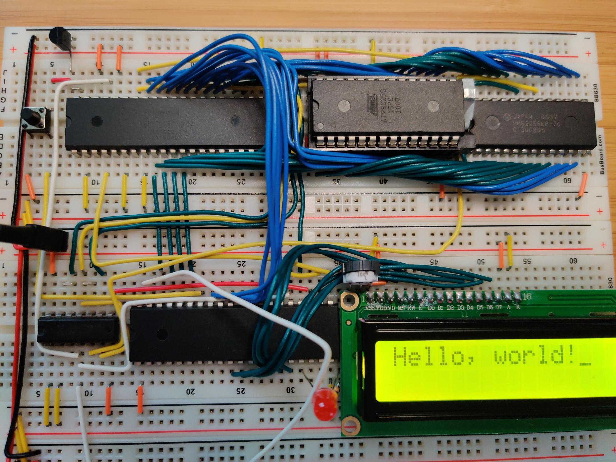
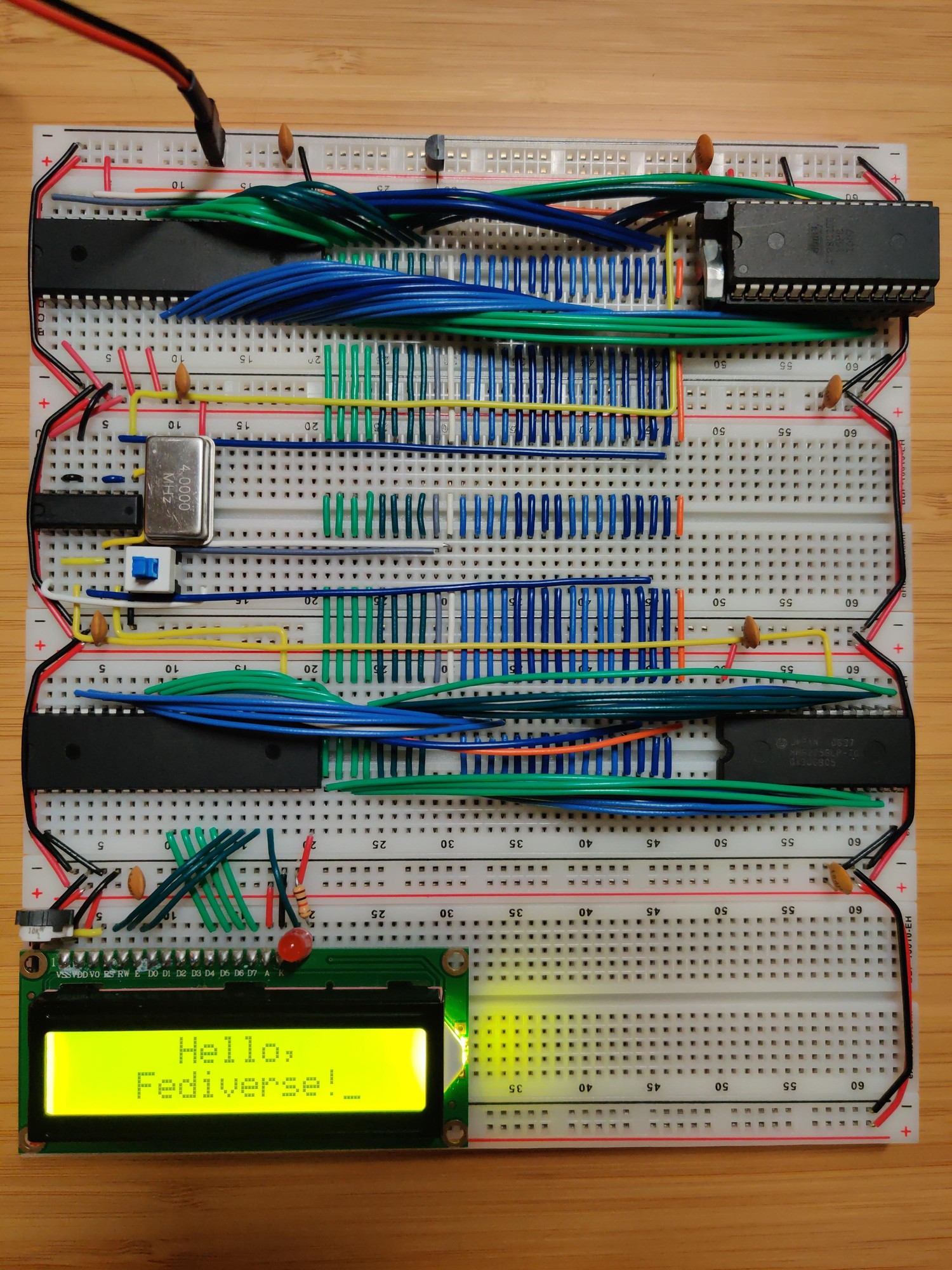
Inspired by some layouts that I'd seen on r/beneater, I went with a layout that has all the bus lines running vertically through the center of each board. Components are placed on the sides and connect to the bus lines instead of directly to each other. There are 27 bus lines:

  • 8 data lines (light green for the low nibble, dark green for high)
  • Reset (gray)
  • Clock (white)
  • 16 address lines (alternating light and dark blue for each nibble)
  • CPU read/write signal (orange)

There's just enough room on the left side for the DIP40 ICs. The DIP28s go on the right, with a few columns to spare. Since the data bus starts at column 21, it aligns nicely with the numeric labels on the breadboard. The 1st data line is at column 21, 2nd line is at 22, 3rd at 23, and so on. I put the reset and clock lines in between the data and address busses in order to maintain this pattern for the address lines: 1st at 31, up to 16th at 46. I guess I could have gotten 0-based indexing instead of 1-based if I had put the DIP40s on the right side, but the 6502 really wants to be on the left side due to its pin layout.

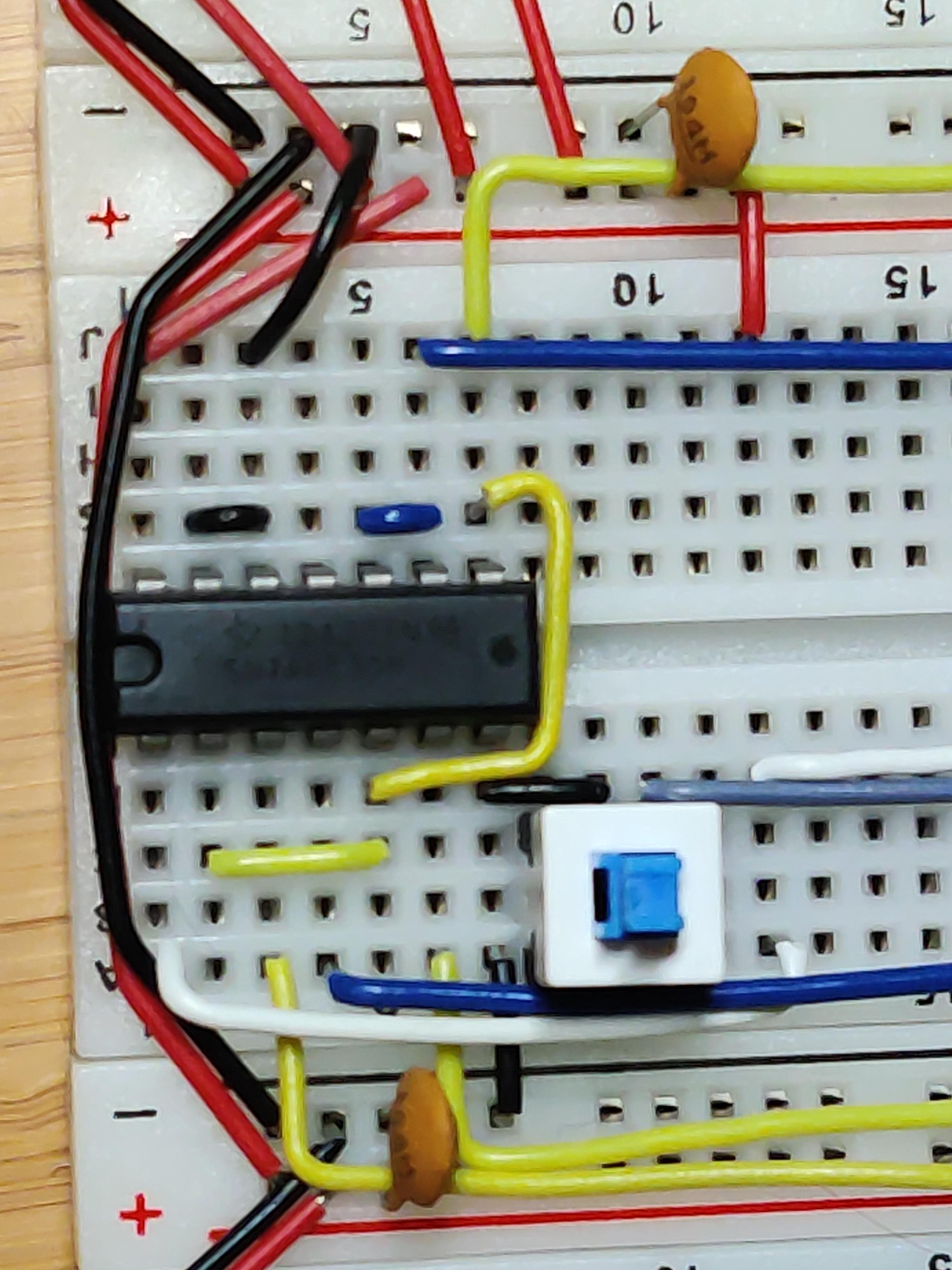
I also did some creative wiring in order to fit the reset button below the oscillator so that it wouldn't take up any extra real estate:

A681824S5Law1RY.jpg

The center pins of the button share a column with the GND pin of the oscillator. The left pins are in the unusable space between the oscillator and the NAND IC. The right pins are in an otherwise unused column that runs underneath the oscillator. Since the reset button doesn't take up any extra space, there's room for an additional DIP14 next to the oscillator, and another two DIP14s or DIP16s to the right of the bus on that board.

A set of breadboards with a 65c02 microprocessor and associated components. An LCD screen on one of the boards reads "Hello, Fediverse!"
18


HI

I'm looking to write a programming guide for general line cortex-M0 TI MSPM0G1106.. For C, covering the main peripherals, SPI, DMA etc..

Using the sphinx book structure.

I'm choosing to write this because, though there are good beginner books for STM32, there's none for TI..

I'm semi experienced in the field.

But I've written article series on other microcontrollers in the past in my blog. Anyone willing to critique them?

Many thanks :)

Here's a risc-v one: https://simplycreate.online/tags/ch592

19


Rescuing vintage microcontrollers from their decades-long purgatory in a drawer.

PS: not my blog.

20


DIY rebuild project for the Tektronix PS503A dual tracking power supply.

The constructed power supply: https://www.paulvdiyblogs.net/2026/03/diy-ps503a-construction.html

PS: not my blog.

21


I barely know anything about electricity. With that said:

I bought this decoration containing a bunch of what looks like LEDs (henceforth "lamp") at a thrift store

It needs 4.5 volts to function, according to the writing on a little etiquette. I wanted to ditch the AAA battery power supply and power it with a DC adapter, so I stripped the DC adapters end and cut off the lamp's cord that goes to the battery case/on off button in order to connect them like so

I even tried to attach the stripped DC wires to the original battery box, thinking that maybe there some circuitry magic going on in the little PCB.

The LEDs do not light up.

Questions:

  1. aren't this wiring of the LEDs weird? It touches itself all the way, which to my very limited knowledge means shorting itself. Unless LEDs work differently?
  2. the wiring of the LEDs seems to be of other material than copper. Is that relevant here?
  3. why isn't this working?

In any case, I'll just rip out the LEDs and put in my own LEDs with wiring that's encased in some insulator, I guess.

Edit: I needed to remove the insulating coating from the LED wiring ends. I did it by burning it off. Thank you all!

22


Do you need 16 bytes of ROM that you can program with a soldering iron? Well, you're in luck!

I'm working on a larger project that I'll hopefully be sharing here soon, and needed something to display hexadecimal digits on a 7-segment LED display. The non-obsolete ICs that I found could only do binary coded decimal, but I need to be able to display A-F as well. An EEPROM truth table can be used for this, but I also wanted to avoid any programmable ICs. I decided to take an old-school approach and create a diode ROM board.

Diode ROM parts

Diode ROM assembled

Diode ROM in use

23


Hello, first time poster (and also no significant EE background, so bear with me).

After receiving a batch of bad USB C PD trigger boards, I decided that it would be better if I made some myself. The design is taken from the CH224K datasheet. However, I am not sure if

  1. the schematic is correct
  2. the PCB is well laid out (I really struggled to fit everything)

Here is the schematic, and here is the PCB. Both are in a Codeberg repo.

24


I've been working on Ben Eater's breadboard 6502 computer project for a little while. The pins on the EEPROM sometimes get bent when I pry it out of the breadboard to reprogram it. I was afraid that they'd break eventually, so I looked into getting a Zero Insertion Force (ZIF) socket to put on the board, which should be gentler on the EEPROM's pins. Ran into a few problems though:

  • The pins on ZIF sockets are too short to seat properly on a breadboard. They're designed to be soldered into a printed circuit board.
  • I found a few designs for adapter PCBs that allow a ZIF socket to be used on a breadboard. They're all sized for the common green ZIF sockets, which take up a lot of extra space compared to the chip that they hold.
  • Aries Electronics makes low-profile ZIF sockets that are very compact, but I couldn't find any adapters designed for them.

I eventually decided to solve that last one myself, and I figured I'd share the design in case anyone else might find it useful:

25


An audio amplifier was once a fairly simple analogue device, but in recent decades a typical home entertainment amplifier will have expanded to include many digital functions. When these break they are often proprietary and not easy to repair, as was the case with a broken Pioneer surround-sound device given to [Boz]. It sat on the shelf for a few years until he had the idea of a jukebox for his ripped CDs, and his returning it to life with a new main board is something to behold.

Internally it’s a surprisingly modular design, meaning that the front panel with its VFD display and driver were intact and working, as were the class AB amplifier and its power supply. He had the service manual so reverse engineering was straightforward, thus out came the main board in favor of a replacement. He took the original connectors and a few other components, then designed a PCB to take them and a Raspberry Pi Pico and DAC. With appropriate MMBASIC firmware it looks as though it was originally made this way, a sense heightened by a look at the motherboard inside (ignoring a couple of bodges).

view more: next ›